A machining drawing carries more decisions than most customers realise: the blank it starts from, the tolerance on each diameter, the finish where a seal or bearing sits. Get those decisions right and the part comes back on schedule at a price that matches the job; get them wrong and either the shop over-engineers a simple bushing or a critical fit ends up too loose to work. Here is how the process runs from blank to inspected part, and what to put on the drawing to keep it efficient.
Choosing the blank: bar, forging or casting
The blank decides more about the final part than the machining itself. Bar stock cut to length is the default for shafts, bushings, axles and any part where grain direction does not matter much. It's fast to source and cheap for one-off and small-batch work. A forged blank is the right call when the part carries cyclic or shock loads: forging works the metal structure through the whole cross-section and aligns the grain flow along the part's contour, raising fatigue strength in stepped shafts, flanges and rings well beyond what the same steel achieves from bar stock. A cast blank earns its place where geometry itself is the point: complex internal cavities, ribbed housings, thin walls. Cut from solid, those shapes would need excessive stock removal and a lot of extra machine time.
The choice also sets the machining allowance: a rough sand casting or an open-die forging needs generous stock on every surface to clean up scale and defects, while a near-net closed-die forging or a permanent-mould casting needs much less, which shortens cycle time and cuts scrap. Specifying the blank type up front, rather than leaving the shop to guess from the finished-part drawing alone, is one of the simplest ways to control both lead time and cost.
From rough cut to finished geometry
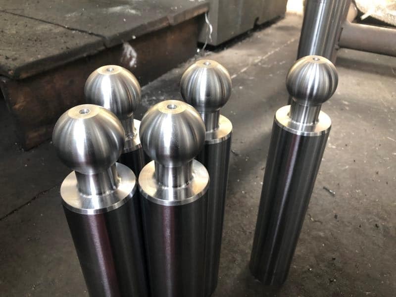
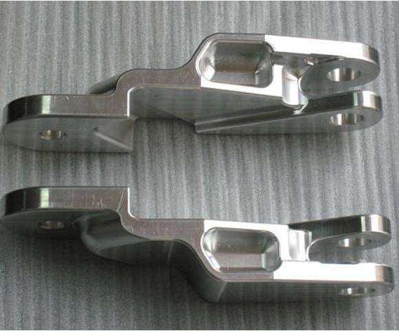
Machining runs in stages, roughing first and finishing last, because each stage releases internal stress differently and a part cut to size in a single pass will often move once that stress lets go. Turning sets the shaft or bushing's main diameters, shoulders, threads and chamfers; our DMG MORI lathes hold this up to Ø500 mm and 1000 mm long, with H6/h6 fits where the part mates with a bearing or seal. Milling handles everything that is not round: flats, pockets, bolt patterns, housings with faces on several sides. It runs in 3 to 5 axes on our Haas centres, holding a repeatable Ra 0.8 µm on finish passes thanks to thermal compensation and Renishaw in-process probing. Drilling and boring bring holes to the fit the drawing calls for, from a clearance hole to a bored seat that has to run true with a shaft. Where a diameter needs to be tighter and smoother than turning alone delivers (typically once heat treatment has hardened the surface), grinding takes over and brings it back inside tolerance. Large parts follow the same logic on different equipment: rods, shafts and housings up to Ø2 m and 16 m long go on our Schiess lathes, with Klingelnberg equipment for finish grinding once a part outgrows standard tooling.
What tolerance actually costs
Tolerance is where quotations most often diverge from customer expectations: a tolerance one grade tighter than necessary can double the machining time on a given feature. IT6–IT7 (roughly ±0.005–0.015 mm depending on diameter) is realistic on our turning and milling centres for series and precision parts without grinding: shaft journals, bushing bores, bolt-pattern positions. Bringing a bearing seat or seal land down to a controlled H6/h6 fit, or holding roundness after heat treatment, moves the job onto a grinding operation. That's a separate setup and a separate line in the cost. Concentricity and run-out between features on the same shaft are commonly held to 0.05 mm; tighter is possible but should be reserved for surfaces that genuinely need it. The practical rule for a drawing: tight tolerances only on diameters and faces that mate with another part (a bearing bore, a seal land, a locating shoulder). Everywhere else, a standard tolerance to ISO 2768 is enough, and it keeps the quotation close to what a simple part should cost.
Inspection before the part ships
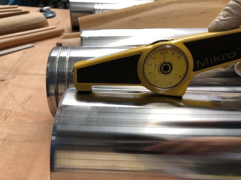
Every stage is followed by a measurement, not just the last one. Catching a diameter out of tolerance after roughing is far cheaper than catching it after grinding. Small and medium parts go through a coordinate measuring machine for geometry, hole position and fit checks; long rods, shafts and large housings are measured end to end with laser trackers and 3D scanners, since a CMM table cannot hold a 16-metre part. The largest components also get a manual check, calibrated rules, bore gauges, micrometers and gauge blocks, as a cross-check on the optical measurement. On request we issue a measurement report against the drawing, which matters for customers who need traceability back to the batch and material certificate.
What to include in your enquiry
A drawing (DXF, STEP or PDF; a dimensioned photo is enough to start a quotation) with the material grade, the tolerance and fit on each functional diameter, the required surface finish and the batch size lets us pick the right blank and machine on the first pass. If a feature's tolerance is driven by a mating part rather than by habit, say so. It often opens a cheaper machining route. With no drawing at all, a physical sample plus the operating conditions is enough to start.
Have a part to machine, from a single prototype to a standing series order? See our CNC machining capabilities or send your drawing to our metalworking division: we reply within one working day.