A hydraulic cylinder looks simple: a tube, a piston, a rod. Sizing one correctly is the hard part. It comes down to matching three numbers to the job — bore, working pressure and pump flow. Get one wrong and the machine either stalls under load or crawls too slowly to be useful. Below: the physics behind a cylinder, worked examples for force and speed, and what to put in a request for quotation so the numbers come back right the first time.
Single-acting, double-acting and telescopic cylinders
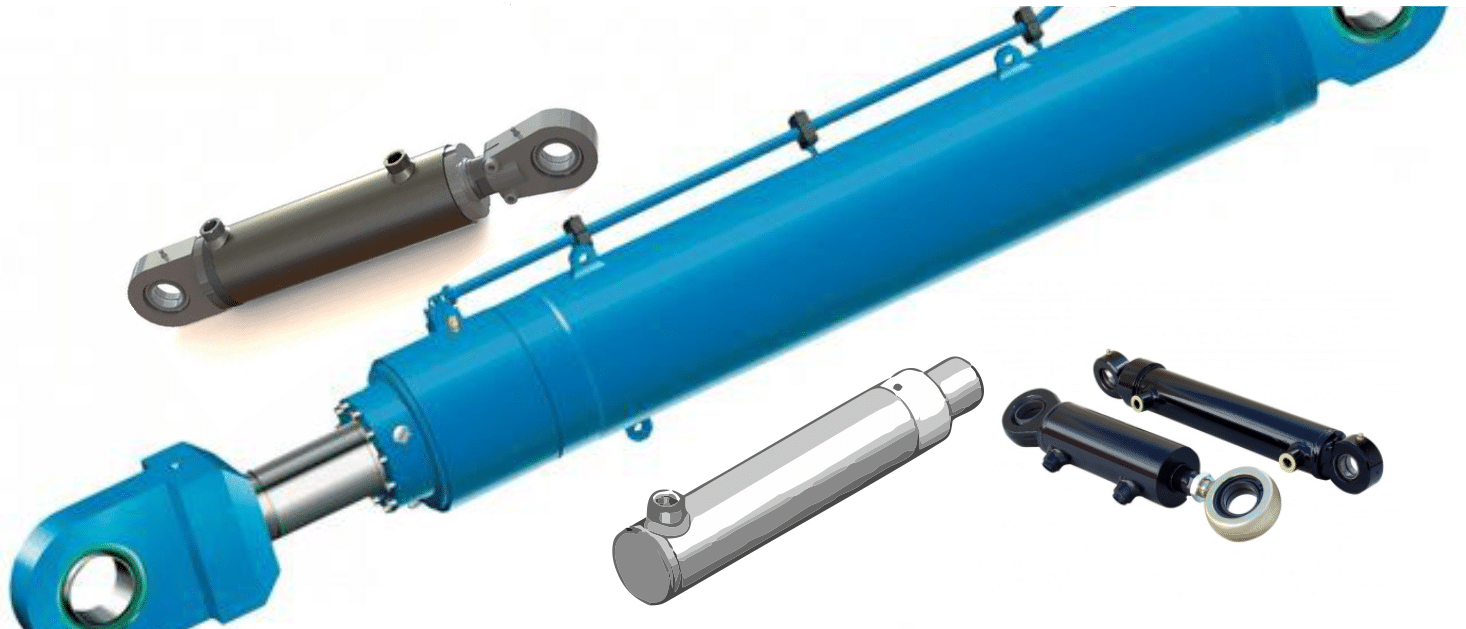
A hydraulic cylinder converts fluid pressure into a straight-line push or pull. How it pushes, and how it returns, depends on the design.
A single-acting cylinder takes pressurised fluid on one side of the piston only. That pressure drives the working stroke; a spring or the weight of the load pulls the rod back. Simplest and cheapest layout there is. It shows up on jacks, tippers and simple lifting frames, but it only pushes one way.
A double-acting cylinder has a port on each side of the piston, so the pump can pressurise either chamber and drive the rod both out and back under power. That is why it is the standard choice across agricultural machinery, road-building equipment and lifting platforms — the operator keeps full control over both directions of travel, not just one.
A telescopic cylinder nests several stages of decreasing diameter inside one another, each stage serving as the barrel for the next. Retracted, it is barely longer than its widest stage. Extended, it delivers a stroke several times its own closed length, which is exactly why tipper bodies, trailers and municipal vehicles rely on it: the installation length is fixed, but the load still needs a long lift.
Force: pressure times area
The force a cylinder produces comes from one relationship: force equals pressure multiplied by the area the pressure acts on.
F = p × A
With pressure in MPa and area in mm², the result comes out directly in newtons (1 MPa = 1 N/mm²). Working pressure is more often quoted in bar, so it helps to remember that 1 bar = 0.1 MPa.
Take a cylinder with a 100 mm bore running at 160 bar (16 MPa) on the extend stroke, where the full piston area is exposed to pressure:
- Piston area: A = π/4 × 100² ≈ 7 854 mm²
- Force: F = 16 N/mm² × 7 854 mm² ≈ 125 700 N ≈ 125.7 kN (about 12.8 tonnes-force)
That is the number that has to clear the load, plus enough margin for friction, side loading and pressure drop in the hoses and valves between the pump and the cylinder.
Why retraction pulls less than extension pushes
On a double-acting cylinder, the extend stroke uses the full piston area. The retract stroke does not: the rod itself takes up part of the piston's cross-section on that side, so pressure only acts on what is left over, a ring-shaped area called the annulus.
With the same 100 mm bore and a 56 mm rod:
- Rod area: π/4 × 56² ≈ 2 463 mm²
- Annulus area: 7 854 − 2 463 ≈ 5 391 mm²
- Retraction force at 160 bar: 16 × 5 391 ≈ 86 300 N ≈ 86.3 kN
That is roughly 69% of the extend force at the same pressure. It comes straight from the rod diameter, nothing more. It is also why bore and rod diameter both belong on a drawing: the ratio between them sets how much force is available on each stroke, and a thicker rod, useful against buckling on long strokes, always costs some retraction force.
Rod speed versus pump flow
Force tells you what the cylinder can push. Speed depends on how fast the pump fills the chamber. Rod velocity is flow rate divided by the area being filled:
v = Q / A
At a pump flow of 60 L/min (1 000 cm³/s) and the same 100 mm bore (78.5 cm²), extend speed works out to roughly 1 000 / 78.5 ≈ 12.7 cm/s, or about 0.13 m/s. The retract stroke fills the smaller annulus area, so the same 60 L/min drives the rod back faster. That is handy on the return stroke, but it has to be factored in when sizing a hydraulic motor or pump for the circuit, because flow and pressure requirements are not the same in both directions.
What to specify in your enquiry
A cylinder quotation comes back accurate on the first pass when the request includes bore and rod diameter (or the force required in each direction), working and maximum pressure of the system, and stroke length together with the closed and open installed length. Beyond that, a few details save a round of questions:
- Pump flow rate, or the required extend and retract speed
- Mounting type (trunnion, clevis, flange) and cylinder orientation in service
- Duty cycle and environment: dusty, marine, high-temperature
Send a drawing, a sketch, or just the parameters above. We size the bore, rod and pressure class to match your load and speed targets. Get in touch and we reply within one working day.